The objective of this experiment is to determine a relationship between the object distance d0, the image distance di, and the image height hi. This can be accomplished by increasing the focal length by an integer value each trial. The first step that must be done is to determine the focal length of the magnifying glass that is being used. This can be determined by taking the convex lense outside where the sun is and continue adjusting the length until the focal length can be determined. Measure this using a ruler and the focal length for the lense was 24.5 cm.
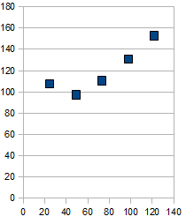
 As the object distance is changed to half the focal length, the focal point could not be seen because the image was blurry and cannot be focused on. Graphs were to be plotted with the object distance vs the image distance with the object distance on the x values and the image distance on the y values.
 This is not a linear graph but the graph of the inverse is more linear:
 Using the computer's best line fit for the equation, the resulting line is y = -.87337x + .03788 which determines a lot about the graph of the inverses. The y intercept of .03788 determines the inverse of the focal length which is simply just 1/y intercept. The slope of the line indicates the relation of the focal point and the object distance. In the form of y = mx + b, the actual equation becomes 1/p = -m(1/q) + 1/f.
Just like any other experiment, there is always a certain amount of uncertainty. Especially with this lab and the lab where the width of a human hair is measured, slight uncertainty results can result in a much larger field of error. The most obvious uncertainty in this experiment comes from the human error. When the focal length was measured outside when using the sun as a source of light, many factors can contribute in giving an inaccurate measurement. However, the trial is done twice to minimize the amount of error given off by measurements. The other factor of uncertainty is basically the same thing, when one measures with the ruler, the measurements will always become off by a small but damaging amount.


